
Opening a CAD program for the first time can be intimidating. The screen may be filled with toolbars, panels, coordinates, unfamiliar icons, and a large empty workspace.
Even simple actions seem to require commands, exact measurements, and settings that do not exist in ordinary drawing applications.
The good news is that beginners do not need to understand the entire program before creating something useful.
CAD becomes much easier when it is approached as a sequence of practical skills rather than a collection of hundreds of commands.
Your first goal should not be to master 3D modeling, produce a complex building project, or memorize every tool. A better objective is to create one accurate 2D drawing from beginning to end.
That small project can teach you how CAD software thinks, how drawings are organized, and how professional technical documents are prepared.
This guide explains the essential first steps, the habits worth learning early, and a simple route from an empty workspace to a complete drawing.
What CAD is Used for
CAD stands for computer-aided design. It is software used to create accurate drawings and digital models of objects, buildings, components, systems, and spaces.
The main difference between CAD and ordinary drawing software is precision. In a graphics editor, you may draw a line until it looks approximately correct.
In CAD, that line can be exactly 2,500 millimeters long, positioned at a defined coordinate, connected to another object at a precise angle, and assigned to a specific layer.
This precision allows CAD drawings to communicate information that can be used for construction, manufacturing, installation, inspection, or approval.
CAD software is commonly used to create:
- architectural floor plans and building details;
- mechanical parts and assembly drawings;
- electrical, plumbing, and ventilation diagrams;
- furniture and interior layouts;
- site plans and landscape designs;
- manufacturing documentation; and
- technical illustrations and workshop drawings.
A beginner does not need to choose a permanent specialization immediately. The basic skills are similar across many disciplines.
Lines, circles, layers, object snaps, dimensions, blocks, layouts, and printing are useful whether you are drawing a room, a machine component, or a piece of furniture.
The most important conceptual change is learning to work with geometry rather than pictures. A CAD drawing is not simply an image. It is a structured collection of objects. Every line, arc, circle, dimension, and text element has properties that can be measured and edited.
Once you understand this principle, the interface begins to feel less complicated. The program is not asking you to draw beautifully. It is asking you to define objects accurately.
Starting With a Small Project
Many beginners spend too much time watching tutorials without completing a drawing. Tutorials are useful, but CAD skills develop much faster when every new command is connected to a practical task.
Choose a first project that is simple enough to finish in one or two sessions. Good examples include:
- a floor plan of a single room;
- a rectangular metal plate with several holes;
- a simple desk or shelving unit;
- a garden layout;
- a workshop arrangement; and
- a basic electrical diagram.
A room plan is particularly useful because it introduces several essential CAD concepts without requiring advanced engineering knowledge.
Start by measuring the room. Record its length and width, wall thickness, door and window positions, and any fixed features. Then create the drawing using real dimensions. If the room is 4,200 millimeters long, draw it as 4,200 units rather than reducing it to fit on the screen.
This introduces one of the most important CAD rules: draw objects at their real size.
Zooming and layouts determine how the drawing appears on the screen or printed page. You should not normally make the geometry smaller simply because the object is physically large.
Before drawing, check the units. Architectural work may use millimeters, centimeters, meters, inches, or feet. Mechanical drawings often use millimeters or inches. Mixing units is one of the easiest ways to create serious errors, so establish them at the beginning.
Next, learn a small number of commands:
- Line for creating individual straight segments;
- Polyline for creating connected segments as one object;
- Rectangle for basic rectangular geometry;
- Circle and Arc for curved elements;
- Offset for creating parallel geometry;
- Trim and Extend for correcting intersections;
- Move, Copy, Rotate, and Mirror for editing; and
- Dimension for communicating size.
You do not need fifty commands during your first project. Ten well-understood tools are more valuable than fifty tools you cannot use confidently.
Drawing Accurately
Beginners often try to work faster before they have learned to work accurately. This produces drawings that look acceptable from a distance but contain gaps, overlapping lines, incorrect dimensions, and objects that do not connect properly.
CAD software provides several systems for preventing these errors.
Use Object Snaps
Object snaps allow the cursor to recognize exact geometric points such as endpoints, midpoints, centers, intersections, and perpendicular positions.
Without object snaps, two lines may appear to meet while actually being separated by a tiny gap. That gap can cause problems later when creating hatches, calculating areas, generating closed contours, or preparing geometry for manufacturing.
Do not rely only on visual placement. Zooming in is not a substitute for snapping to the correct point.
Coordinates
You do not need to become a mathematics expert, but you should understand the basic coordinate system.
Absolute coordinates position an object relative to the drawing origin. Relative coordinates define a new point from the previous point. Polar coordinates use a distance and angle.
For example, a line can be created by specifying that its next point is 1,000 units away at an angle of 90 degrees. This is often faster and more accurate than moving the cursor manually.
Ortho and Polar Tracking
Ortho mode restricts cursor movement to horizontal and vertical directions. Polar tracking helps draw along specified angles.
These tools are especially useful when creating walls, mechanical profiles, grids, and other structured geometry. They reduce dependence on visual judgment and make drawing behavior more predictable.
Measuring and Checking
Use measurement tools regularly. Do not assume that an object is correct because it looks correct.
Check distances, angles, radii, and coordinates as the drawing develops. Finding a mistake after five minutes is much easier than discovering it after the entire project has been dimensioned and prepared for printing.
Choosing Beginner Software
The ideal beginner application should provide enough professional structure to teach transferable skills without requiring an expensive commitment at the start.
It should support accurate 2D drawing, layers, object snaps, blocks, dimensions, layouts, and a commonly used file format. A traditional interface can also be helpful because it introduces workflows found in many professional CAD systems.
One practical option is nanoCAD Free. It provides a classic desktop CAD environment with native DWG support and core tools for creating and editing 2D engineering drawings. It includes layers, dimensions, reusable blocks, external references, text, tables, coordinate tools, and familiar command-based workflows.
The free edition is intended for non-commercial projects and is best viewed as a learning and basic drafting environment rather than a modern advanced 3D modeler.
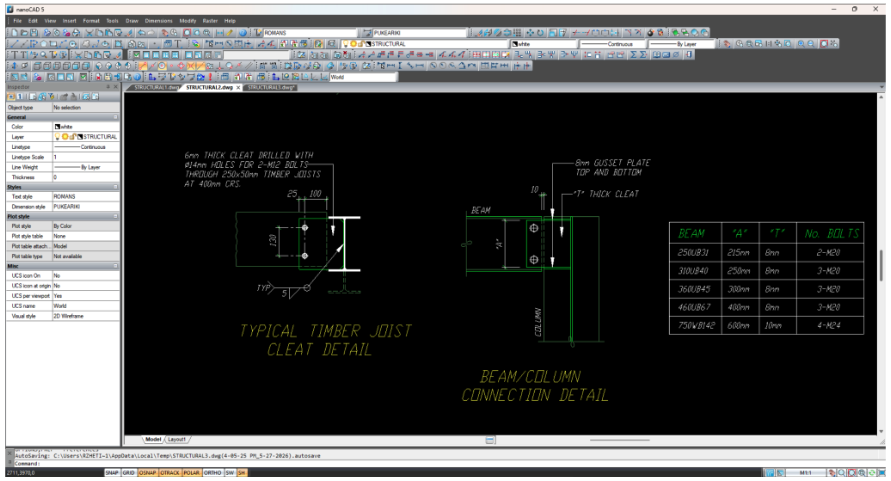
This makes nanoCAD useful for students, hobbyists, teachers, home renovators, and beginners who want to understand conventional DWG-based drafting. Working in such an environment teaches concepts that remain relevant if you later move to a current commercial CAD platform.
However, software choice should follow your actual goal.
If your priority is traditional 2D drafting, choose a program with strong drawing and documentation tools. If you mainly want to design objects for 3D printing, a parametric solid modeler may be more appropriate. If you are studying architecture, you may eventually need BIM functionality in addition to standard CAD.
Do not choose software only because it has the longest feature list. A beginner benefits more from a program that can be installed, understood, and used consistently.

Organize Drawings with Layers
Layers are one of the first professional habits worth developing.
A layer can be understood as a category of objects. In a floor plan, separate layers might be created for walls, doors, windows, furniture, dimensions, electrical elements, and text. In a mechanical drawing, layers might separate visible outlines, centerlines, hidden geometry, dimensions, and construction lines.
Layers allow you to control:
- object color;
- line type;
- line thickness;
- visibility;
- printing behavior; and
- whether objects can be edited.
A common beginner mistake is placing every object on the default layer. The drawing may still work when it is small, but editing becomes increasingly difficult as more information is added.
Create only the layers you need. A first project may require five or six rather than dozens. Give them clear names such as WALLS, DOORS, FURNITURE, DIMENSIONS, and TEXT.
Avoid vague names such as Layer 1 or New Layer. A layer name should tell another person what kind of information it contains.
It is also good practice to assign properties through layers instead of changing every object individually. For example, all objects on the dimension layer can share the same color and line weight. If the standard changes, you can update the layer rather than modifying hundreds of separate elements.
Blocks for Repeated Objects
A block is a reusable group of drawing objects.
Suppose your room plan contains six identical chairs. You could draw and copy the same geometry six times, but using a block is more efficient. The chair becomes a defined object that can be inserted repeatedly.
Blocks are commonly used for:
- doors and windows;
- furniture;
- electrical symbols;
- plumbing fixtures;
- bolts and standard components;
- title blocks; and
- logos and drawing labels.
Blocks reduce file complexity and improve consistency. When used correctly, they also make revisions easier.
Some blocks can contain attributes such as component numbers, names, room labels, or equipment information. You do not need to master attributes immediately, but understanding basic block creation will already improve your drawings significantly.
Before creating a block, decide where its insertion point should be. A door might use the hinge as its insertion point. A table might use its center. A mechanical symbol might use the point where it connects to another object.
A sensible insertion point makes the block easier to position accurately.
Adding Dimensions
Dimensions are not decorative labels. They communicate the measurable requirements of the design.
A useful drawing should provide enough information for another person to understand the size and position of important elements without guessing.
Before adding dimensions, confirm that the geometry itself is correct. If you dimension too early, every later change may require additional corrections.
Learn the main dimension types:
- linear dimensions for horizontal and vertical distances;
- aligned dimensions for sloped geometry;
- angular dimensions;
- radius and diameter dimensions; and
- arc-length dimensions.
Use a dimension style to control text size, arrowheads, units, decimal precision, spacing, and other properties. Consistency is more important than visual decoration.
Avoid dimensioning the same distance repeatedly unless there is a clear reason. Duplicate or contradictory dimensions can make technical documentation less reliable.
A floor plan might include overall room dimensions, wall positions, door and window widths, and critical installation distances. A mechanical drawing may need overall dimensions, hole diameters, center distances, radii, and tolerances.
The required information depends on what the drawing will be used for.
Model Space and Paper Space
Model space is where the actual geometry is created. Objects are normally drawn there at full size.
Paper space, usually organized through layouts, is where the drawing is prepared for printing or publishing. A layout represents a sheet of paper and may contain a title block, notes, and one or more viewports showing the model at selected scales.
This distinction confuses many beginners, but it solves an important problem.
Imagine drawing a building that is 20 meters wide. You cannot place the building itself on an A3 sheet at full size. Instead, you draw the building at its real dimensions in model space and display it through a viewport at a scale such as 1:50 or 1:100.
The geometry remains accurate. Only its representation on the sheet is scaled.
For a first project, create one layout and one viewport. Select the paper size, choose the viewport scale, position the drawing, and test the print preview.
This exercise connects the digital model to the final technical document.
Common Mistakes
Most early CAD problems are caused by workflow habits rather than difficult commands.
One mistake is drawing approximately instead of entering exact values. Another is ignoring object snaps and creating nearly connected geometry. Beginners also tend to place everything on one layer, explode blocks unnecessarily, or change object properties individually instead of using styles and layers.
Other common problems include:
- starting without checking units;
- drawing the same object several times by accident;
- creating excessive layers with unclear names;
- using too many different text and dimension styles;
- scaling model geometry to make it fit on paper;
- forgetting to save regularly;
- editing the wrong layer;
- printing without checking line weights and scale; and
- downloading complex templates before understanding their structure.
The solution is not to work more slowly forever. It is to build a repeatable process.
For each project, establish units, create layers, draw the geometry, verify dimensions, add annotations, prepare the layout, and inspect the final output. Repeating this sequence turns isolated commands into a reliable workflow.
A Three-Week Learning Path
During the first week, focus on navigation, selection, basic geometry, coordinates, and object snaps. Complete one simple drawing.
During the second week, practice editing tools, layers, properties, text, hatches, and dimensions. Redraw the same project more efficiently or choose a slightly more complex one.
During the third week, learn blocks, external references, layouts, viewports, and printing. Try to produce a complete technical sheet rather than only geometry in model space.
After that, choose a direction based on your goals. Mechanical design may lead toward parametric 3D modeling and assemblies. Architecture may lead toward construction documentation and BIM. Manufacturing may require tolerances, standards, and CAM. Surveying may require coordinates, terrain models, and geospatial data.
The foundations remain useful in every case.
Conclusion
Learning CAD is not mainly about memorizing software. It is about learning to describe objects accurately, organize technical information, and communicate a design so that another person can understand and use it.
Your first drawing does not need to be impressive. It needs to be accurate, organized, and complete.
Start with a simple real-world project. Work in the correct units. Use object snaps rather than visual guesses. Separate information with layers. Reuse repeated geometry as blocks. Add dimensions carefully. Prepare the drawing on a layout and print it at a defined scale.
Once you can complete that process confidently, the empty CAD workspace will no longer feel intimidating. It will become what it is meant to be: a precise environment in which ideas can be converted into buildable, measurable, and shareable designs.
Leave a Reply